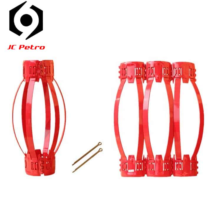
Bow Spring Centralizer

83 / 100

Bow Spring Centralizer

Types: Single. Double,Turbolizer,Intergral Bow Spring Centralizer

Size: 2 7/8“ to 26″

WhatApp: +86 158 0546 5460

Patrameter

Size (in)Hooping I.D.(mm)Hooping Thickness (mm)Hooping Height (mm)Total Length (mm)Max.O.D.(mm)Spring Pieces
4-1/2″×6″ 1143–590-120650±501525
5″×6-1/2″1273–590-120650±501655
5-1/2″×6-1/2″1403–590-120650±501655
5-1/2*8-1/2142-1483–590-120650±50225±55
6-5/8″×8-1/2″1683–590-120650±502186
7″×9-1/2″1783–590-120650±502436
7*9-5/8181-1863–590-120650±50255±56
7*8-1/2181-1863–590-120650±50235±56
7-5/8″×9-1/2″1943–590-120650±502436
7-5/8″x9-7/8″2443–590-120650±502536
8-5/8*12-1/4223-2283–590-120650±50330±58
9-5/8*12-1/4250-2553–590-120650±50330±58
10-3/4*12-1/4274-2763–590-120650±50330±59
13-3/8*17-1/2342-3473–590-120650±50450±511
14-3/8″×18-3/4″3653–590-120650±50550±512
16″×20″4063–590-120650±50550±512
18-5/8*24476±13–590-120600±50610±512
20*26510±13–590-120600±50660±512

Types

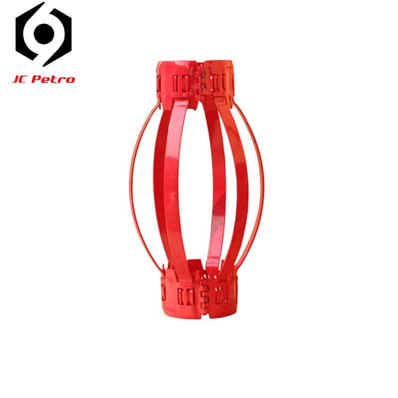
Single Bow Spring Centralizer

Single Bow Spring Centralizer

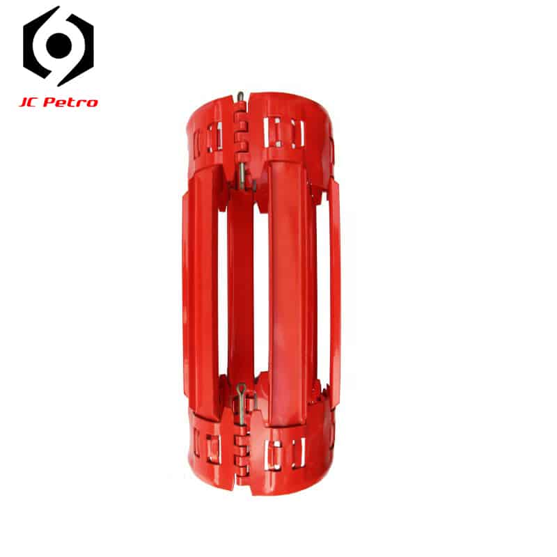
Double Bow Spring Centralizer
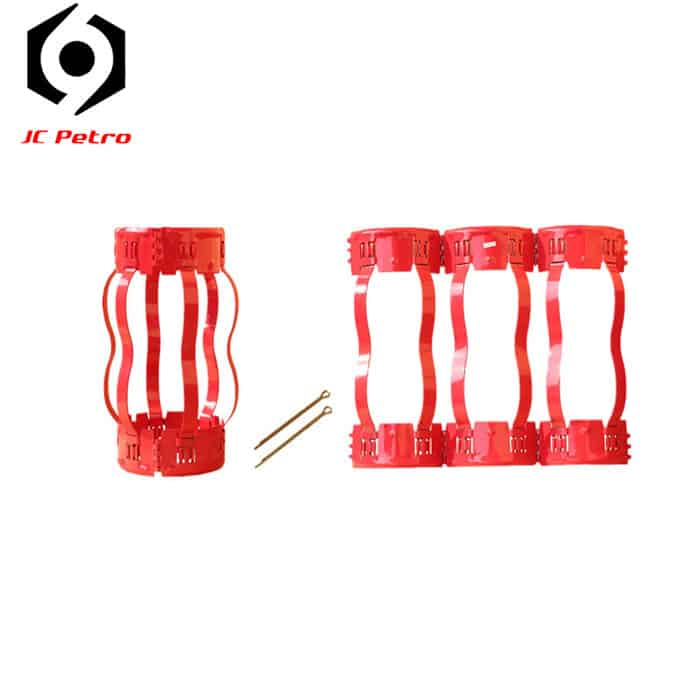
Double Bow Spring Centralizer

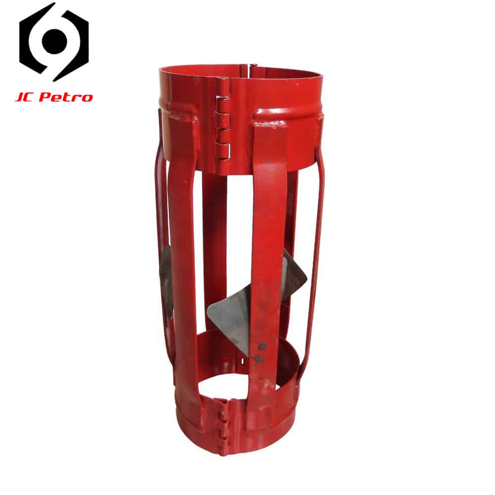
Turbolizer Centralizer
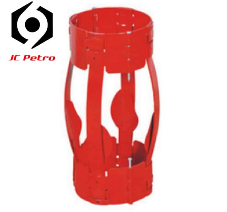
Turbolizer-Bow-Spring-Centralizer

One-Piece Intergral Centralizer
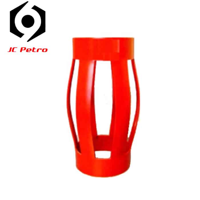
One-Piece-Intergral-Centralizer

Description

Welded bow spring centralizers provide excellent downhole durability and performance. These centralizers feature heat-treated, spring-steel bows that are welded to rigid end collars.

Feature

  • High-performance bows provide maximum standoff in multiple locations of the annulus, providing the best possible conditions for primary cement to achieve zonal isolation;
  • All centralizer sizes have been tested and validated to meet American Petroleum Institute (API) 10D requirements, providing reliability and durability during operations;
  • Non-welded design can withstand most wellbore environments, providing operational flexibility;
  • Bow configurations are available in various heights and sizes suitable for most applications and providing a variety of bow configurations for special applications;
  • Suited for vertical and deviated wellbore.

Patrameter

Size (in)Hooping I.D.(mm)Hooping Thickness (mm)Hooping Height (mm)Total Length (mm)Max.O.D.(mm)Spring Pieces
4-1/2″×6″ 1143–590-120650±501525
5″×6-1/2″1273–590-120650±501655
5-1/2″×6-1/2″1403–590-120650±501655
5-1/2*8-1/2142-1483–590-120650±50225±55
6-5/8″×8-1/2″1683–590-120650±502186
7″×9-1/2″1783–590-120650±502436
7*9-5/8181-1863–590-120650±50255±56
7*8-1/2181-1863–590-120650±50235±56
7-5/8″×9-1/2″1943–590-120650±502436
7-5/8″x9-7/8″2443–590-120650±502536
8-5/8*12-1/4223-2283–590-120650±50330±58
9-5/8*12-1/4250-2553–590-120650±50330±58
10-3/4*12-1/4 274-2763–590-120650±50330±59
13-3/8*17-1/2342-3473–590-120650±50450±511
14-3/8″×18-3/4″3653–590-120650±50550±512
16″×20″4063–590-120650±50550±512
18-5/8*24″476±13–590-120600±50610±512
20*26″510±13–590-120600±50660±512

Description

High quality double bow centralizers are made of special alloy steel and hot formed in totally controlled heat treatment plant to achieve the uniform hardness all over.
Spec and performance index of bow spring casing centralizer meet API Spec 10D.

The double bow centralizer is connected by pin when in use, the unfolded centralizer can be stacked flatly for convenient storage and transportation.

Feature

  • Provides superior standoff with reduced running forces when compared to conventional bow-spring centralizers;
  • All centralizer sizes have been tested and validated to meet American Petroleum Institute (API) 10D requirements,providing reliability and durability during operations;
  • Suited for vertical and deviated wellbore; Primarily suited for horizontal and directional wellbores .

Patrameter

Size (in)Hooping I.D.(mm)Hooping Thickness (mm)Hooping Height (mm)Total Length (mm)Max.O.D.(mm)Spring Pieces
4-1/2″×6″ 1143–590-120650±501525
5″×6-1/2″1273–590-120650±501655
5-1/2″×6-1/2″1403–590-120650±501655
5-1/2*8-1/2142-1483–590-120650±50225±55
6-5/8″×8-1/2″1683–590-120650±502186
7″×9-1/2″1783–590-120650±502436
7*9-5/8181-1863–590-120650±50255±56
7*8-1/2181-1863–590-120650±50235±56
7-5/8″×9-1/2″1943–590-120650±502436
7-5/8″x9-7/8″”2443–590-120650±502536
8-5/8*12-1/4223-2283–590-120650±50330±58
9-5/8*12-1/4250-2553–590-120650±50330±58
10-3/4*12-1/4274-2763–590-120650±50330±59
13-3/8*17-1/2342-3473–590-120650±50450±511
14-3/8″×18-3/4″3653–590-120650±50550±512
16″×20″4063–590-120650±50550±512
18-5/8*24476±13–590-120600±50610±512
20*26510±13–590-120600±50660±512

Description

Turbolizer Centralizer are designed with deflector blades. The special blades are riveted to heat-treated bows and are designed to deflect fluid flow in a turbulent spiral.

This effect helps break up drilling mud when running casing and improves mud removal during circulation. It provides additional fluid agitation for cementing benefits in critical zones.

Features

  • Equipped with right or left handed deflector fins which contributes to a high-quality primary cement job;
  • Meet API Specification 10D requirements; 
  • Fins are heat treated spring steel.

Specification

Specificationcasing size (mm)Hole Size (mm)Inner Diameter (mm)Outer Diameter (mm)
4-1/2″×5-1/2″ 114140118.3140
4-1/2″×5-3/4″114146118.3146
4-1/2″×6″114152118.3152
4-1/2″×6-1/8″114156118.3156
4-1/2″×6-1/4″114159118.3159
5″×6″127152131152
5″×6-1/8″127156131156
5″×6-1/4″127159131159
5-1/2″×6-1/2″140165143.7165
5-1/2″×7″140178143.7178
5-1/2″×7-1/2″140191143.7191
5-3/4″×7-1/2″146191150191
5-3/4″×8-1/2″146216150216
6-5/8″×8-1/2″168216172.3216
6-5/8″×8-11/16″168221172.3221
6-5/8″×9-5/8″168245172.3245
7″×8 1/2 “178216181.8216
7″×8-11/16″178221181.8221
7″×9-5/8″178245181.8245
7-5/8″×8-11/16″194221197.7221
7-5/8″×9-5/8″194245197.7245
9-5/8″×11-5/8″245295248.5295
9-5/8″×12-1/4″245311248.5311
12-3/4″×15-1/2″324394327.8394
13-3/8″×15-1/2″340394343.7394

Description

The new one-piece style centralizers are made from one piece of steel plate. The plate is cut by laser, rolled for forming,welded using high-temperature wire saw.Then the bows of centralizer are formed by an hydraulic machine; at last the centralizers are powder coated after heat treatment.

Features

  • One-piece construction design;
  • Sizes are available from 2 7/8” to 20” ;
  • High stand-off(+85°/〇) and high restoring force;
  • Straight bows can provide maximum lateral support;
  • Completely fit with casings in a ledge wellbore condition;
  • Reduces frictional drag and torque;
  • Max O.D. is the same as wellbore;
  • Zero starting force;
  • All performances can exceed API 10D requirements;

Description

SpecificationCasing size (mm)Hole Size (mm)Inner Diameter (mm)Outer Diameter (mm)
4-1/2″×6″ 114152118152
5″×6-1/2″127165132165
5-1/2″×6-1/2″ 140165142165
5-1/2″×8-1/2″140216142218
6-5/8″×8-1/2″168216172218
7″×8-1/2″178216182218
7″×9-1/2″178241182243
7-5/8″×9-1/2″194241198243
7-5/8″x9-7/8″”194251198253
9-5/8″×12-1/4″244311249311
10-3/4″× 12-1/4″273311278311
12 3/4″×17-1/2″324445328445
13-3/8″×17-1/2″340445344445
14-3/8″×18-3/4″365476369476
16″×20″406508410508
18-5/8″×24″473610474610
20″×26″508660512660

Get a Free Quotation