Hydraulic Liner Hanger
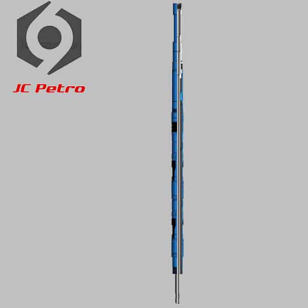
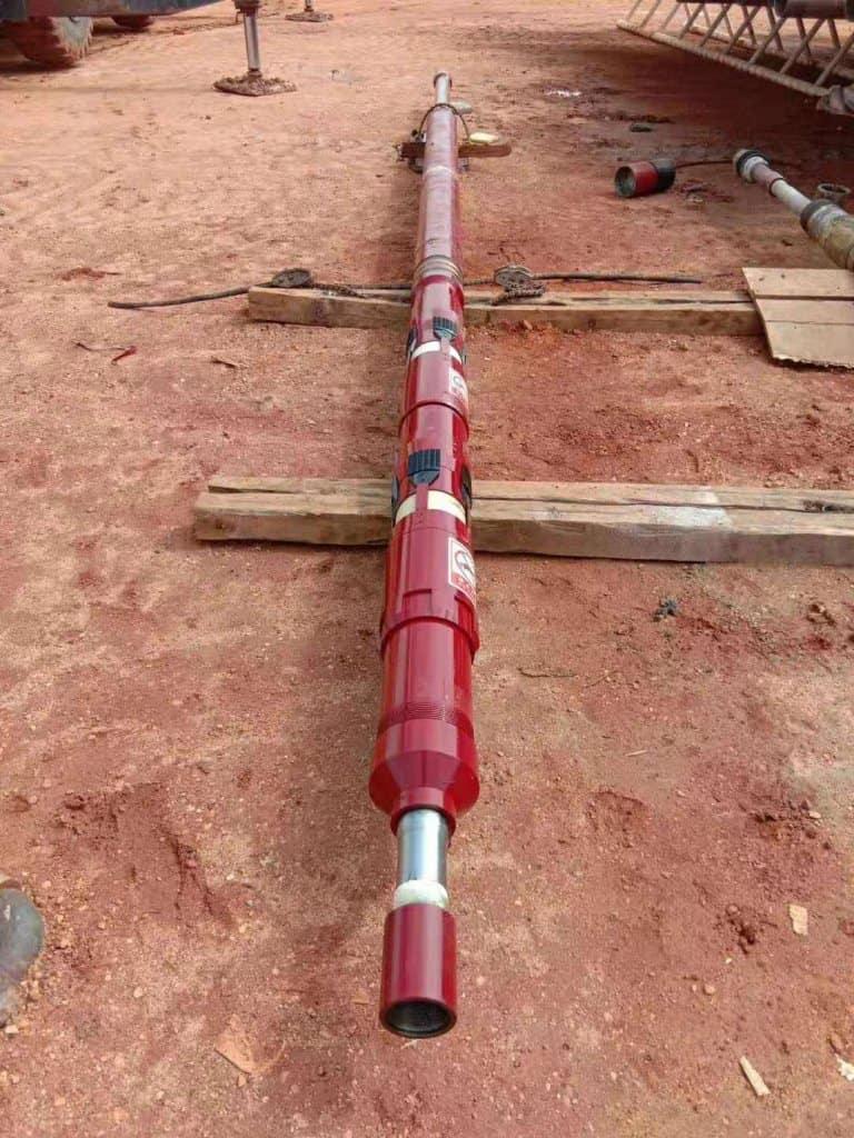
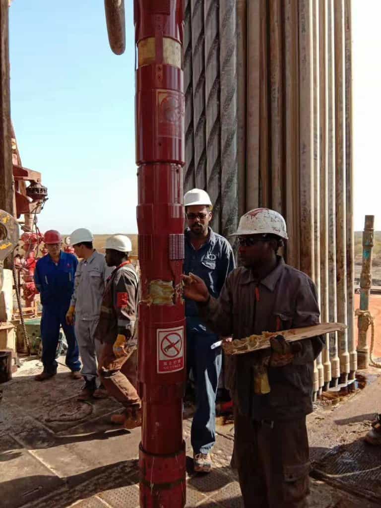
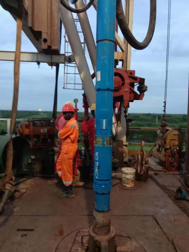
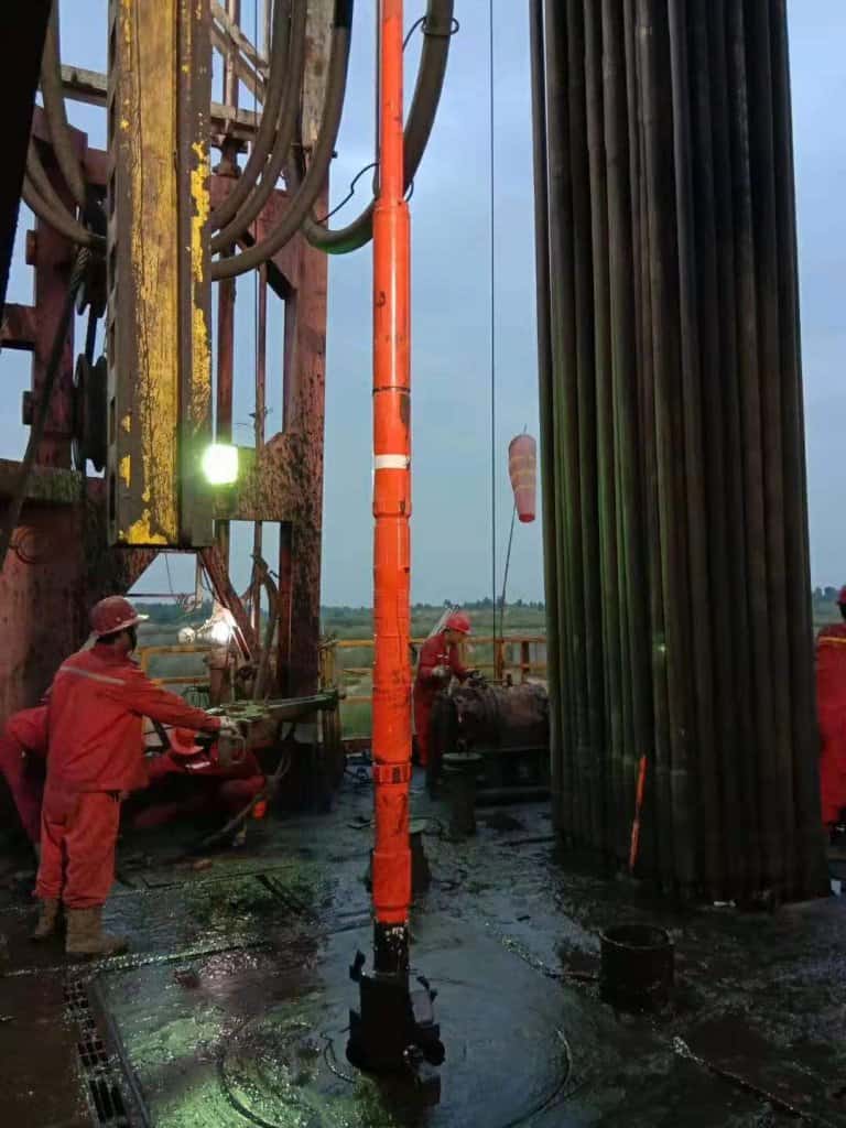
Hydraulic Liner Hanger is designed with single/double cone and single/double row slips structure. It is hydraulically set by applying pressure through the run-in string. After brass ball is dropped to ball at in landing collar, high pressure fluid acts on piston inside cylinder and move slips upward to set position.
We are one of hydraulic liner hanger manufacturers.
4 types of Liner Hangers Hydraulic :
- 1. SSX-A Hydraulic Liner Hanger
- 2. SYX-A Hydraulic Liner Hanger
- 3. XGS-A Hydraulic Liner Hanger
- 4. DYX-A Hydraulic Liner Hanger
WhatsApp: +86 158 0546 5460
The types of Hydraulic Liner Hanger
- 1. SSX-A Hydraulic Liner Hanger Double Cone, Double Cylinder and Double row slips structure)
- 2. SYX-A Hydraulic Liner Hanger Double Cone and Double row slips Structure)
- 3. XGS-A Hydraulic Liner Hanger(Single Cone and Single row slips Structure)
- 4. DYX-A Hydraulic Liner Hanger ( Single Cone and Single row slips Structure)
1. SSX-A liner hanger Description
SSX-A liner hanger, designed with double cones, double cylinders and double-row slips, is hydraulically set by applying pressure through the run-in string. After brass ball is dropped to ball seat in landing collar, high pressure fluid acts on piston inside cylinder and move slips upward to set position.
| Specification,mm | Φ244.5 X Φ177.8mm/Φ139.7mm | Φ339.7mm X Φ244.5mm |
| Rated Load,t | 160 | 240 |
| Sealing Capacity,MPa | 25 | 25 |
| Shearing Pressure of Pins in Cylinder,MPa | 7-8 | 7-8 |
| Casing Wall Thickness,mm | 10.03 11.05 11.99 | 9.65 10.92 12.19 |
| Casing Weight,Kg/m | 59.52 64.73 69.94 | 54.5 68 85 |
| Body Max O.D.,mm | 215 | 308 |
| Body Min I.D.,mm | 155 | 220.5 |
2. SYX-A Liner Hanger Description
SYX-A Liner Hanger, designed with double cone and double row slips structure, is hydraulically set by applying pressure through the run-in string. After brass ball is dropped to ball seat in landing collar, high pressure fluid acts on piston inside cylinder and move slips upward to set position.
| Specifications, mm | Φ244.5×Φ177.8/Φ139.7 |
| Rated Load, t | 160 |
| Sealing Capacity, MPa | 25 |
| Shearing Pressure of Pins, MPa | 7~8 |
| Casing Wall Thickness, mm | 10.03 11.05 11.99 |
| Casing Weight, kg/m | 59.52 64.73 69.94 |
| Body Max O.D., mm | 215 |
| Body Min I.D., mm | 155 |
3. XGS-A Hydraulic liner Hanger Description
XGS-A Hydraulic liner Hanger is hydraulically set by applying pressure through the run-in string. A setting ball is circulated and dropped to ball seat built into the lauding collar. Applied pressure acts on the internal piston and moves ships up the cone to the set position.
XGS-A Hydraulic Liner Hanger Technical Parameters
| Specifications, in/ mm | 5.1/2″x 4″ / Φ139.7×Φ101.6 5.1/2″x 3 1/2″ / Φ139.7× Φ88.9 |
| Rated Load, t | 30 |
| Sealing Capacity, MPa | 35 |
| Shearing Pressure of Pins, MPa | 7~8 |
| Casing Wall Thickness, mm | 7.72 9.17 |
| Casing Weight, kg/m | 25.30 29.76 |
| Body Max O.D., mm | 117 |
| Body Min I.D., mm | 85 |
4. DYX-A Liner Hanger Description
DYX-A Liner Hanger, designed with single cone and single row slips structure, is hydraulically set by applying pressure through the run-in string. After brass ball is dropped to ball at in landing collar, high pressure fluid acts on piston inside cylinder and move slips upward to set position.
DYX-A Hydraulic Liner Hanger Technical Parameters
| Specifications,(in) | 7″×10 3/4″ | 7″×9 5/8″ 5 1/2″×9 5/8″ | 5 3/4″×7 5/8″ 5 1/2″×7 5/8″ | 5″×7″ 4 1/2″×7″ |
| Rated Load, KN | 1800 | 1200 | 800 | 500 |
| Sealing Capacity, MPa | >35 | >35 | >35 | >35 |
| Shearing Pressure of Pins, MPa | 7~8 | 7~8 | 7~8 | 7~8 |
| Casing Wall Thickness, mm | 10.16 11.43 12.57 | 10.03 11.05 11.99 | 9.52 10.92 12.7 | 9.19 10.36 11.51 |
| Casing Weight, kg/m | 67.70 75.89 82.58 | 59.52 64.73 69.94 | 41.19 50.15 58.03 | 38.69 43.15 47.62 |
| Body Max O.D., mm | 242 | 215 | 165 | 152 |
| Body Min I.D., mm | 155 | 155 | 121.4 | 108.6 |
