JC perto is a manufacturer of Two Stage Hydraulic Cement Collar with API certificate and after sale service.
1.General information about the product
The two stage hydraulic cement collar is a tool for performing the cementing of oil and gas wells in two stages.
The first stage cement is displaced through the bottom of the casing. And generally the cementing is displaced to a position in the annulus from the bottom of the casing to a position below the stage cementing collar.
The second stage cement is pumped into the annulus through the stage cementing collar ports. That have been opened to allow this displacement. The opening of the ports is generally performed hydraulically through increasing the internal casing pressure to shear the shear pins and open the sleeve.
A mechanical device, called a free fall opening device, can be dropped into the casing from the surface. It allows to gravitate into the stage cementing collar. Then pressure is applied to open the cementing ports in the stage cementing collar. Once the second stage cement has been displace from inside the casing into the annulus above the stage collar. A closing plug, which has been introduced into the casing on top of the second stage cement, lands in the stage collar, and through the application of internal casing pressure, shears off another set of shears pins, allowing the cementing ports to be closed. And subsequently a locking ring is engaged to permanently close the cementing ports in the stage cementing collar.
After the cement has become hard, a drill bit is lowered into the casing. And any remaining cement, in addition to the plugs that have been used during the operation of the tool, are drilled up. And the cuttings are circulated out of the casing and collected at the surface.
Before use of the equipment, the equipment documentation shall be read !
2.MAIN TECHNICAL DATA
2.1Two Stage Hydraulic Cement Collar Main sizes and parameters
| Nominal casing size | 127mm / 5 inch |
| Nominal casing wall thickness | 9.19mm |
| Type of Steel | API P-110 |
| Outside collar Diameter Maximum | 148mm |
| Drill out diameter Maximum | 108.6mm |
| Cementing Port Diameter | 25.4mm |
| Number of cementing ports | 4 |
| Internal pressure maximum | 10000 Psi |
| External Pressure maximum | 9200 Psi |
| Flowrate (optimum) | 1.6Cubic Meters per minute |
| Body Yield strength (axial) | 124700Psi |
| Casing Thread connection | API LTC |
2.2 operation of the equipment
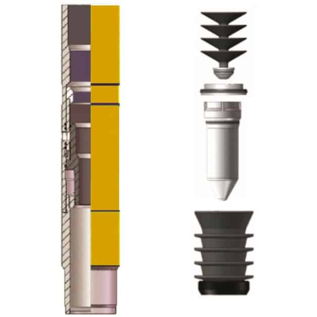
Equipment
This hydraulic stage tool is furnished with accessories consisting of shut-off baffle(landing collar). The flexible first stage shut-off plug, free fall opening device (FFOD) and closing plug. The free fall opening device is furnished as a back-up tool for opening of the stage collar mechanically provided that the deviation at the tool is 15 degree or large. A baffle plate (landing collar)can optionally be used for landing. The flexible first stage shut-off plug and is manufactured to allow it to be installed in non premium casing threads. Such as buttress, 8 round and LTC threaded couplings.
Inspection
Inspect Stage Collar and auxiliary equipment upon arrival at location. Remove collar from box and remove plastic covering to inspect the tools and accessories.
Check the collar for signs of damage on the outside diameter and for damaged threads.
Check the Free Fall Opening Device (if ordered), flexible first stage shut-off plug, Closing Plug to verify that they will seat properly in Stage Tool.
The cementing head also needs to be checked through verifying that type of release pin. That is being used in the cementing head will allow for preloading of the plugs. Or if the lid of the cementing head will have to be removed and the plugs manually released during the cementing operations.
If the release pin extends a minimum of 75% the distance across the internal bore of the cement head and is at least 40mm in diameter then the flexible first stage shut-off plug maybe preloaded.
If the release pin does not meet these minimum requirements. Then do not preload the flexible first stage shut-off plug as vacuum may cause the plug to be sucked past the release pin.
If unsure, do not load the flexible first stage shut-off plug.
Also check the cementing head for the presence of a pressure equalization channel or rod. That will prevent abnormal pressure differential across the flexible first stage shut-off plug when loaded into the cement head.
If the plug release mechanism is not operable, or the release pin is not sufficient to retain the plug. And an equalizing channel is not present then do not preload the second stage Closing Plug.
STAGE COLLAR HYDRAULIC OPENING PRESSURE SETUP
The stage collar opening pressure should exceed by at least 5 Mpa above the maximum differential pressure expected across the stage tool while circulating and cementing. Do not exceed safe internal pressure ratings of the casing and cementing equipment.
Tool has an opening sleeve with 5 locations for installation of opening shear pins. The stage collar is preloaded with the number of shear pins that will require 18 Mpa / 2600 psi to open hydraulically. The closing sleeve will require 10Mpa / 1500 psi to close. All pressures are based upon pressure to overcome the differential pressure at the stage collar at the time of opening and closing of the inner sleeve.
Operating Procedure
1. Install the Baffle plate (landing collar) a minimum of one joint above the float equipment.
2. Install the stage tool at desired location in casing string.
(Do not place tongs on stage tool)
3. Land casing, circulate hole clean and pump pre-wash as required.
4. Open the cementing manifold and install the first stage flexible lead plug with by-pass nose, with bypass nose down into the cementing head. Push it down so the top of the plug is below the lower inlet port in the cementing manifold. The flexible first stage shut-off plug maybe pre-loaded if the cementing head has a plug retainer bar that extends past the centre line of the cementing head.
If the cement head retainer bar does not extend 75% across the internal bore of the cementing head. The flexible first stage shut-off plug should not be pre-loaded into the head.
5. Mix and pump first stage cement. The pump rate must be slowed to .3 to .5 Cubic meters per minute as the first stage flexible lead plug with by-pass nose is pumped through the stage collar.
6. Release the flexible first stage shut-off plug on top of first stage cement. (Cement lines may be pumped out prior to displacement)
7. Pump pre-calculated amount of displacement fluid, land flexible first stage shut-off plug into baffle plate (landing collar), noted by sudden pressure increase. And pressure up to 4mpa over circulating pressure to ensure plug has landed. (The shut-off plug should be pumped through the stage tool at flow rates of .3 – .5 cubic meters per minute maximum).
8. Release pressure and check float valves for backflow. With floats holding proceed or wait for cement to set. Apply pressure to casing until stage tool opens. (Refer to number of shear screws installed in hydraulic sleeve) Surface opening pressure will vary due to differential pressure at the tool.
9. When stage tool opens, establish circulation and condition hole. If the first stage plug has not landed in the baffle plate and it is undesirable to displace additional fluid, the determination can be made to use the free fall opening device to open the stage collar.
If the orientation of the stage collar is less than 15 degrees and fluid density is not higher than 1.3. Then the opening device will gravitate into the stage collar.
As the orientation angle increases and or the fluid density increases it is less likely that the opening device will freely gravitate to the stage collar and mechanical assistance would be required to locate the free fall opening device into the stage collar to effect opening.
If mechanical assistance is required extreme caution in respect to the diameter of the tool used to assist the free fall opening device into the stage collar must be reviewed to ensure it will freely push the bomb into the lower seat without get caught on the upper closing seat of the stage collar.
10. Verify you are pumping through the stage tool by comparing circulating pressure recorded just prior to the shut-off plug landing.
11 . Pump pre-wash as required, and mix and pump cement.
12. Drop closing plug. (Cement lines may be pumped out prior to displacement). The plug may be released from the plug container if it has been pre-loaded or released manually after opening the plug container. Verify that the plug has left the head. Cement lines may or may not be pumped out before dropping this plug. It is preferable to pump out the lines after the closing plug is released to spot some cement on top of the closing plug.
13. Pump pre-calculated amount of displacement fluid to land closing plug in stage tool. (The closing plug should be landed at a flow rate of approx. .5 cubic meters per minute).
14. When closing plug seats, continue pumping until the pressure indicated in the attached guide is reached. ( Higher pressures may be required, do not exceed the safe limits of the casing or surface equipment)
15. Hold pressure for a minimum of 5 minutes, release pressure and check for backflow.
16. If excessive backflow is observed, “run-into” the stage tool with a higher pump rate and /or pressure. Check again for closure
Note:
If stage tool fails to close, it is recommended that the casing be shut-in at surface until the cement sets up.
If the free fall opening device is used, time for the device to gravitate into the stage collar should be calculated. A normal rate of drop is about five minutes per 300 meters in 1.15 specific gravity fluid. If the fluid has higher specific gravity calculate the percentage increase over 1.15 specific gravity and apply this percentage to the calculated drop time. (Example if the specific gravity is 1.5 then the calculated percentage difference is 30% higher. The calculated dropping rate of bomb would be (100%-30% = 70%) 210 meters per 5 minutes. The use of thicker walled heavier weight casing will also affect the rate of free fall. The opening device dropped in 177.8mm – 32.2 Kg./M will free fall faster than in 52.1 Kg./M. casing.
DRILLING RECOMMENDATIONS
PREPARATION:
Apply Thread Lock on thread of float equipment, the first 3 to 5 joints of casing above the float equipment. The Stage Collar and 1 joint above the Stage Collar. Do Not use an excessive amount of thread lock in the box end of the float equipment or stage tool.
Pump some cement slurry on top of the first stage and closing plugs to ensure they are embedded in cement. This will prevent the plugs from rotating during drill out.
Use of a three-cone, long-milled tooth rotary bit is preferred for drilling out the stage collar and plugs. The bit with a configuration for use in medium to soft formations is preferred. Mills bits maybe used, but will have lower penetration rates.
Do not drill in an automatic mode, use manual control at all times during drill out. The use of a junk basket to catch drilled particles is acceptable and/or a casing scraper if drilling production casing. Reamers and stabilizers installed close to the bit will keep the bit on target.
DRILL OUT
Drill in the range of 40-60 RPM. Caution: NEVER EXCEED 90 RPM. Apply 35-50 Kilograms of drilling weight per millimeter of bit diameter.
DO NOT SPUD ON TARGET
Use a pump rate that will circulate cuttings without decreasing bit weight on the target. (A pump rate of .1 liter/second per millimeter of bit diameter is a good starting point.)
DO NOT USE EXCESSIVE PUMPING RATES
Maintain at minimum of 4.5 Mpa / 650 PSI per square millimeter of bit surface.
Raise and lower the bit occasionally while drilling to clear junk from the bit.